1. Creating a Custom AXI IP Core
1.1. Packaging Custom IP
Xilinx provides a large library of premade IP cores that cover a multitude of applications. However, sometimes it is best to create and modify our own cores to suit specific needs, such as creating an emulation environment. Instead of instantiating peripherals in Verilog, we can instead take advantage of the plug-and-play nature of the AXI protocol to easily connect them to an AXI master through a SmartConnect. This article will step through the process of packaging a custom peripheral using the IP Integrator.
Note
If you need a refresher on the AXI protocol, check here.
1.2. A Simple 8-Bit Counter
As the FPGA ‘Hello World’, a simple 8-bit counter is the perfect introductory example for a custom IP block without the need for a development board.
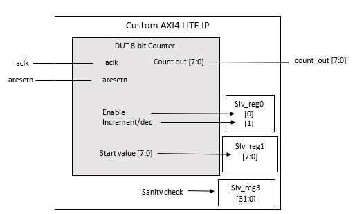
Block Diagram of our counter
Our first device under test (DUT) will be an 8-bit counter with five inputs: clock, enable,
reset, increment/decrement, and a start value, as well as one output - the current
count value. The counter will follow these conditions:
The
enableflag, when HIGH, will allow the count to change; otherwise, it will keep the same value.When a new start value is entered, the counter will automatically start incrementing or decrementing from that new value.
There is no default start value, so an initial start value must be given.
The
resetflag will reset the count to the given start value.
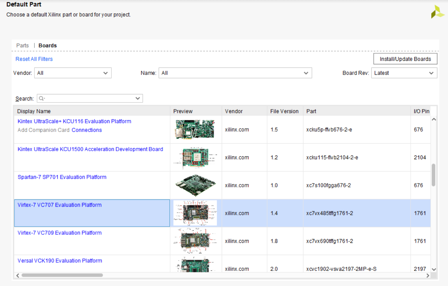
To create this counter, first create a new RTL project and define its directory. For this example, we will use the VC707 evaluation board, but other FPGA boards can be used, like the KC705.
After the project opens, go to Add Sources and select Add or Create Design Sources.
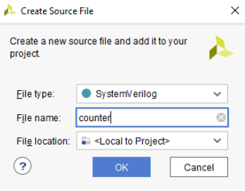
Create a new file, select the desired HDL (we will use SystemVerilog here), and name the file as counter.
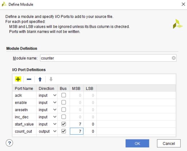
Our new DUT counter.sv will be created. A pop-up window will appear, prompting to define a module
and specify I/O ports. Customize the counter as so and accept.

Make counter_out a register and add in the counter logic.
  //timescale 1ns/1ps

  module counter(
  input aclk,
  input enable, //will enable or disable count
  input aresetn, //will reset count back to start value
  input inc_dec, //will indicate wheather increment count or decrement count. inc count is 0, dec count is 1
  input [7:0] start_value, //value to start counting from
  output reg [7:0] count_out //count value
  );

//local registers
  reg [7:0] count_next; //next count value
  reg [7:0]prev_start_value=start_value;

  always @(posedge aclk)
      begin
      if(aresetn ==0 || prev_start_value!=start_value) //reset mode or new start value
          begin
              count_out =start_value; //reset count out to start value
              prev_start_value=start_value; //set prev start value to start value
          end
      else //reset=1, no reset
          begin
          if(enable==1) //enable is high a
              begin
              if(inc_dec==0) begin//and incdec is low
                  count_next=count_out+1; //increment next value
              end
              else begin //inc_dec is high
                  count_next=count_out-1; // decrement next value
              end
                  count_out=count_next; // set output equal to next value
          end
          else count_out=count_out; //same value if no enable
          end
      end
  endmodule
Counter Testbench
Now that we have instantiated our design, we will simulate it using a simple testbench.
As a refresher, a test bench is HDL code that allows you to provide a documented, repeatable set of stimuli that is portable across different simulators.
After the project opens, go to Add Sources and select Add or Create Simulation Sources.
Create a new file, select the desired HDL (we will use SystemVerilog here), and name the file as counter_tb.
Our new testbench counter_tb.sv will be created.
Create a testbench that practices all functions of your custom DUT. For this simple counter example, we will create a testbench that exercises the enable/disable, reset, increment/decrement, start value, and lastly ensure that the counter rolls over correctly.
    //timescale 1ns/1ps

module counter_tb();
    //create necessary variables
    reg aclk;
    reg enable;
    reg aresetn;
    reg inc_dec;
    reg [7:0]start_value;
    wire[7:0] count_out;

    //create DUT
    counter DUT(
        .aclk(aclk),
        .enable(enable),
        .aresetn(aresetn),
        .inc_dec(inc_dec),
        .start_value (start_value),
        .count_out(count_out)
    );

    //define clk
    always begin
        #5 //delay 5ns
        aclk=~aclk;//should be a 100MHz clk
    end

    initial begin
    //will turn in after 100ns and start inc from af for 100ns
    //then reset and new start value at c0 will increment for 50
    //disbale for 50ns
    //enable again and then decrement
        aresetn=0;//turn on reset
        enable=0;//not enabled
        aclk=0;
        start_value=8'haf;//set a start value
        inc_dec=0;//will increment

        #100 //100ns delay
        aresetn=1;//turn off reset
        #20
        enable=1;//turn on enable

        #100
        aresetn=0;
        start_value=8'hc0;//new start value
        aresetn=1; //lift the reset
        #50
        enable=0;
        #50ns
        enable=1;
        inc_dec=1;
    end
endmodule
To run this very simple testbench, follow the instructions below:
On the left sidebar, right click on Run Simulation and select Run Behavioral Simulation.
The waveform should have automatically opened. It may be hard to see what you are looking at because the simulation might be very zoomed in. If this is the case, ensure to zoom out so you can see several clock cycles of
aclk.
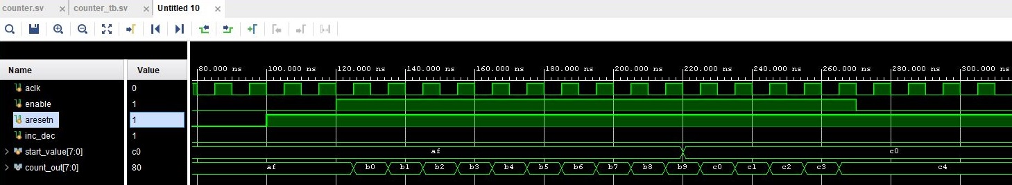
Working Start Value, Increment, Decrement, and Enable
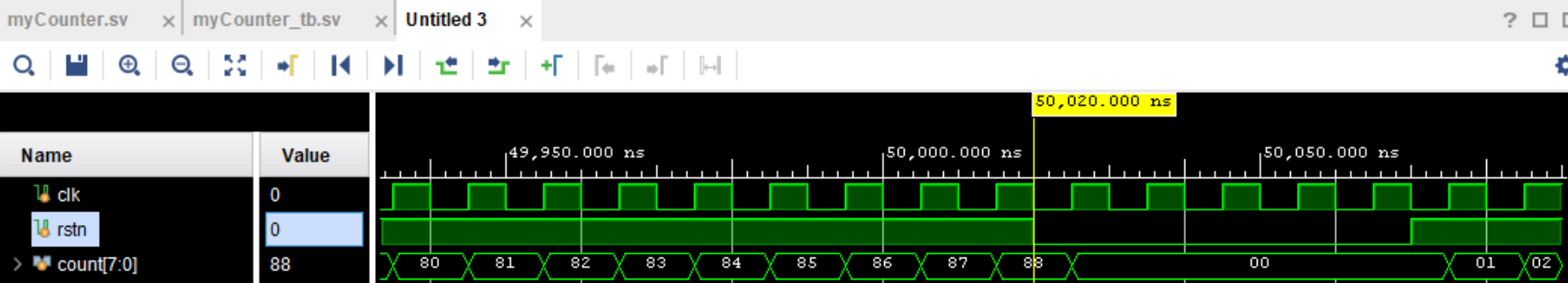
Working Reset
Once the simple counter slave DUT is working as expected, ensure you know where to find to the project files in your computer. we recommend closing the project to avoid confusion while following the future instructions.
1.3. Packaging a Custom AXI4Lite IP
This section focuses on how to create a custom AXI4Lite IP and how to correctly instantiate the DUT.
This specific example will focus on a simple counter. Referring to our previous counter block diagram,
this is where the enable, increment/decrement, and start value will be mapped to the AXI4Lite
slave registers. In addition, the inputs of aclk and aresetn will be connected to the AXI clock
and reset. Afterwards, we will add a sanity check for slave register 3 along with an output port count_out.
It is important to note that because the reset and registers will be tied to the AXI4Lite slave registers and
that aresetn will reset all the slave register values. This means that once a reset is performed, the
enable, inc/dec, start value, and count_out will all be set back to 0. An AXI Write is required
to change any values from 0 after a reset has occurred.
Because our custom IP is very simple and does not generate any commands to send to another peripheral, we will be creating only a Slave IP. Sn example of when we would want to use both a slave and a master interface in the same IP would be if we wanted to have this same counter, but with the additional features of being able to read and write to an external memory, as we will guide you through in this section here
Create a new project and name as desired. This is the project that will be the main project for this simple counter IP. Select the same board and settings as selected previously. Once the new project is opened, go to Tools and select Create and Package New IP… A new window will open and explain the features. Click Next and select Create AXI4Peripheral. Name the IP as desired and select Next. Adding and subtracting new interfaces can be done with the + and - buttons. Remember to select the desired Interface Type, Interface Mode, Data Width, and Number of Registers. For a counter, modify the parameters as shown in the image below. These parameters mean that there will be only one interface - an AXI4Lite slave with 4 registers, each with a data width 32 bits. When finished, click Next.
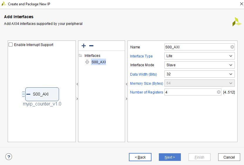
Add Interfaces to AXI4 peripheral
Select Edit IP and click Finish. A new design source and IP Packager will open. The next step is to add our DUT (counter) into this project. In order to do this select Add Sources and select Add or Create Design Sources. Select next and Add Files to add your DUT. Once you have correctly selected your DUT, it will appear in the window. When you select Finish, the file will be successfully added to your Sources window.
DUT successfully added to Design Sources
The DUT needs to be correctly instantiated into the custom AXI IP. In order to do this, open the file ending with _S00_AXI
as it’s name. When we created this AXI Peripheral, we selected 4 registers with 32 bits of data. Those registers are
shown in this file as slv_reg0-3. These are where we are going to store the necessary data for our instantiated DUT.
The changes that should be made are listed below:
Important
If you wish to download the _S00_AXI file directly, go here.
Create a User Defined output port, which will be a wire and 8 bits wide, called
count_out.
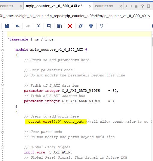
Adding Output Port to the Slave File
Scroll down and instantiate the DUT under where it says Add User Logic Here. Include the necessary parameters. In this counter, tie
slv_reg0bit 0 toenable,increment/decrementtoslv_reg0bit 1 andstartvalue toslv_reg1bits 7-0. Tie the clock and reset to the slave AXI clock and reset.
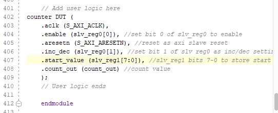
Adding User Logic DUT to the Slave File
Use slv_reg3 as a sanity check. Set
slv_reg3to abcd1234. This means that everytimeslv_reg3is read it will always be abcd1234.
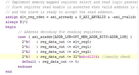
Adding a Sanity Check to the Slave File
The custom counter is correctly instantiated into the file ending in _S00_AXI. Now it is necessary to instantiate
this counter into the top file. There are two steps necessary to do this:
We must add our output port
count_outin the ports of the AXI slave bus interfaceS00_AXI.
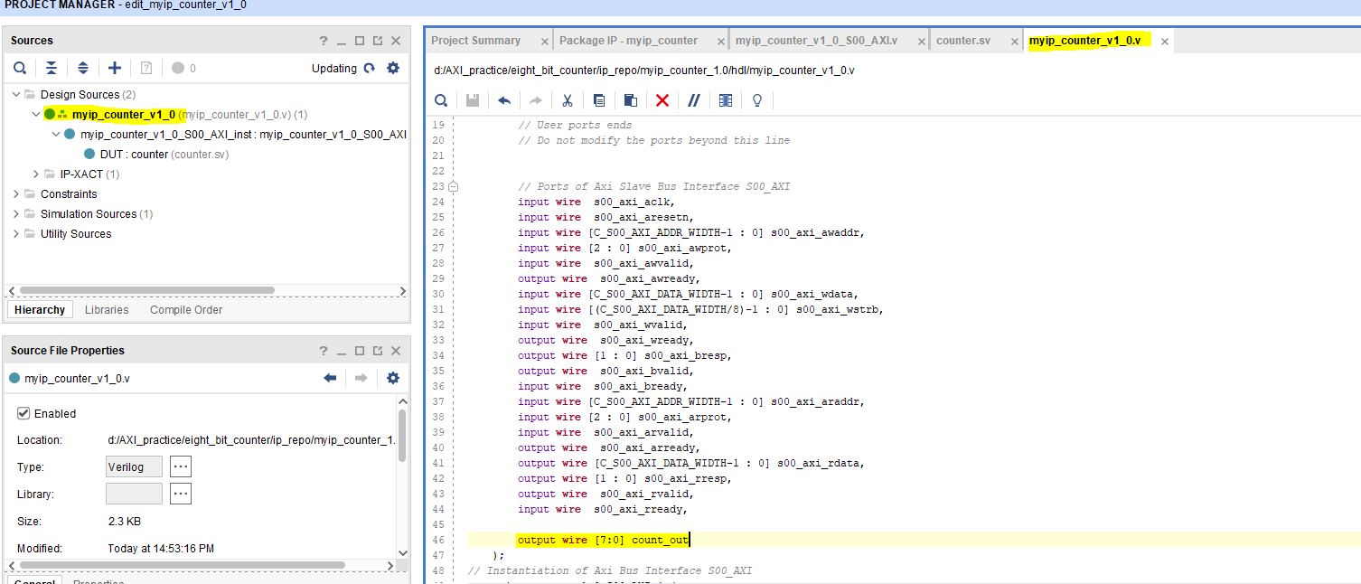
Adding Output Port to Top File
Add the ports to the instancation of the AXI bus interface
S00_AXI.
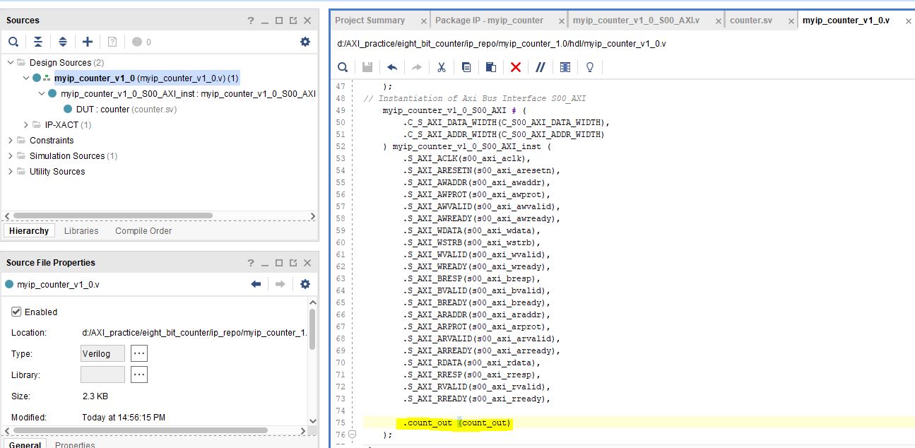
Adding Ports to AXI Bus Interface in Top
Important
If you want to download the top file instead, go here.
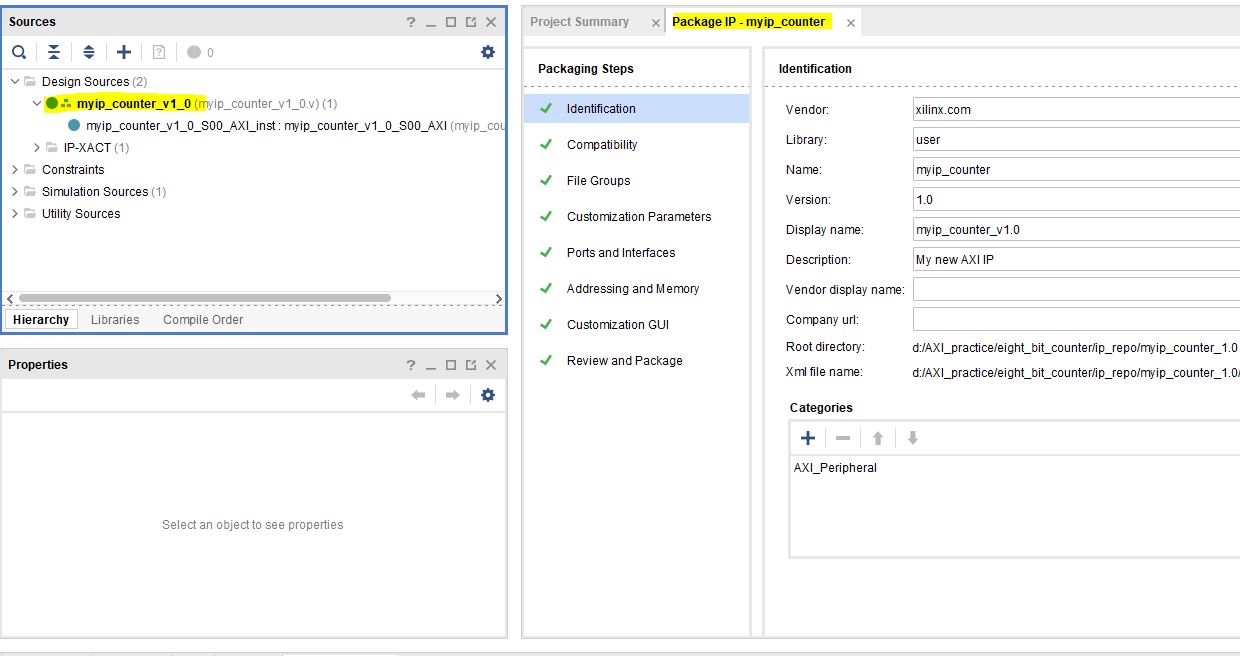
Now that the DUT is correctly instantiated, the next step is to open the Package IP tab. Under Packaging Steps, verify that every category has a green check mark next to it. In order to achieve this, click on a category such as File Groups and select Merge changes from File Groups Wizard. This will automatically merge the changes made. Continue this with all of the necessary categories.
Once at the Review and Package category, click IP has been modified and then click Re-Package IP at the bottom of the window. A new window will pop up and tell you the directory of your IP. Keep note of this directory in case you might need to add the repository to a new project.
Once the IP has been correctly packaged, you will be prompted Do you want to close the project. Select Yes and the project that you were editing the IP will be closed, however, the “main project” that we created at the beginning of this section will still be open.
1.4. Adding a Custom AXI IP to a Design
This section will walk through how to add the packaged custom IP to a block diagram and test its functionality with AXI VIP.
If you have been following along with us, congratulations! The custom IP is now correctly packaged! The project made earlier in this tutorial should still be open. The repository for our IP was automatically added to this project, so integrating it into a block design is very straightforward.
Select Create New Block Design and name it as desired.
A new window will open. Select the + to add IP into the block design. Look for the custom IP that was just created and add it to the block design.
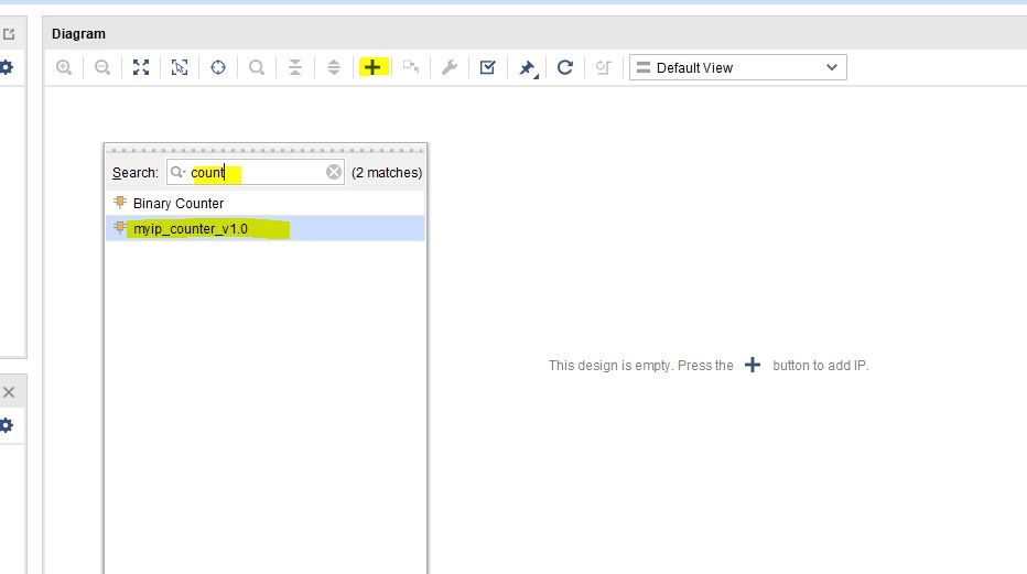
Add Custom IP to Block Diagram
Add the AXI VIP from the IP catalog. Double click on the AXI VIP and make it a Master and change the interface mode to manual for protocol, and change it to AXI4LITE. Select OK.
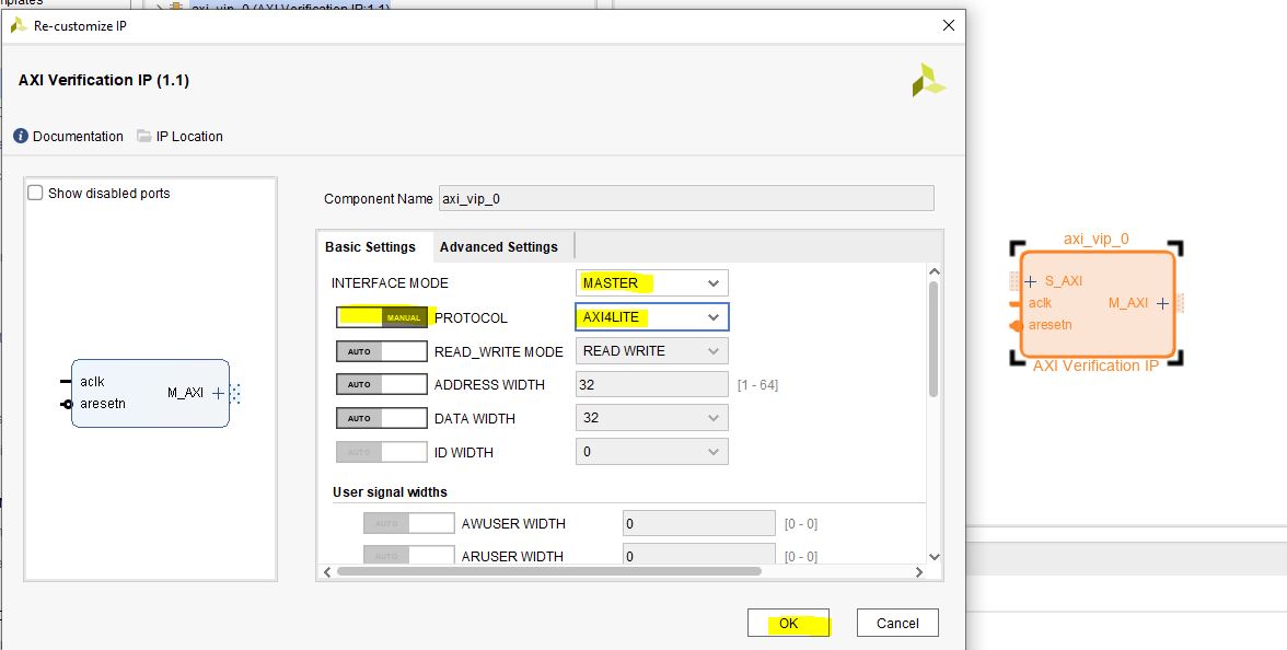
Add AXI VIP Parameters
Connect the Master port of the AXI VIP to the slave of the counter.
Make the
clockandresetports of the AXI VIP external. In order to do this, right click on the signal such asaclkof the AXI VIP and select Make External. Once the clock and reset of the AXI VIP are external, drag the clock and reset of the counter IP to connect with the appropriate external signal.On the counter IP, make the
count_outports external.
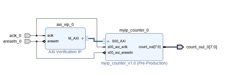
Simple Counter Block Diagram
Go to the Address Editor tab and right-click on the custom AXI IP. Click Assign. This will automatically assign the address range for this IP. Keep note of it for the test bench; for example, the assigned base address may be a hex value like
0x44A0_0000. If the address editor is not apparent on your screen, complete the next step and you will recieve an error to assign addresses, and the address editor will appear.Go back to the block diagram and right-click on a blank spot in the design. Select Validate Design.
The next step is to create a wrapper file which turns the block diagram into HDL. To do this go to the Sources and right-click on the source for your block diagram (the default name is
design_1or something similar). Select Create HDL Wrapper and then Let Vivado manage wrapper and auto-update.The next step is to create a testbench to ensure the custom AXI IP works as intended.
1.5. Creating a Testbench for a Custom DUT
This section will walk through the necessary parts to make a testbench.
After the project opens, go to Add Sources and select Add or Create Simulation Sources.
Create a new file, select the desired HDL (we will use SystemVerilog here), and name the file as desired (this example is called counter_ip_tb.
Our new testbench counter_ip_tb.sv will be created.
When using the AXI VIP, there are two packages that you must import.
Note
The packages will be underlined in red and appear as a syntax error. This is a Vivado bug and can be safely ignored.
The first package axi_vip_pkg::*; needs to be copied directly. The second package is a hierarchy path that may be different for you.
The file hierarchy should be found from the sources tab.
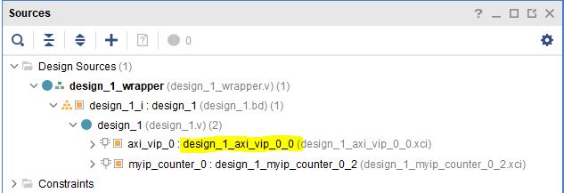
AXI VIP Component Hierarchy
An example of the two imported packages for this hierarchy are shown below:
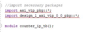
Import Packages Example
Be sure to import these packages before the module your_testbench_name.
Next, after the autogenerated module counter_ip_tb(); (the counter_ip_tb will be replaced with what you named your testbench), make sure to
add a clk and reset bit and initialize them both to zero.
After this, create names for both the addresses and data that will be sent (this is optional, you can instead insert the addresses and data directly into the commands).
Next, instantiate the block design from the wrapper file.
From there, it is necessary to create a master agent vip, create an agent, and start the agent (using appropriate hiarchy as well).
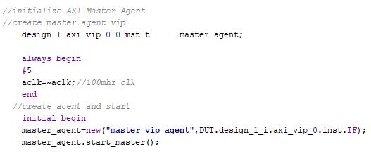
Create and Start Master Agent for VIP
This master agent is for the AXI Verification IP and allows for you to simulate the custom IP recieving read and write transactions. It is important to recognize that the AXI VIP is just for simulation purposes and allows us to test our custom DUT without building the entire infrastructure around it.
From here, create the necessary logic to test all aspects of the custom DUT. It is important to note that this logic will be executed sequentially, so ensure you have delays large enough to allow the necessary transactions enough time to complete. For this simple counter example, the code is provided and also avalible for direct download below.
Because this simple DUT is an 8-bit counter, with an enable, increment/decrement, start value, and sanity check register the testbench below exercises all of these features. Here is a quick outline of the testbench logic:
Enables the counter in increment mode
Write a start value to the counter and read it back to ensure it worked
Write a new value AF to the start value
Disable the counter
Enable it again in increment mode
Change to decrement mode
Write new start value 11 to counter
Read sanity check register (should always be abcd1234 even if write to it)
Exercise the reset
Enable counter and read value of start register
Important
If you want to download the testbench file directly, go here.
//timescale 1ns / 1ps

//import necessary packages
import axi_vip_pkg::*;
import design_1_axi_vip_0_0_pkg::*;

module counter_ip_tb();

bit aclk = 0;
bit aresetn = 0;
logic[7:0] count_out;

xil_axi_ulong base_reg=32'h44A00000; //slv_reg0 is base reg enable bit is LSB, reg increment/decrement setting is bit 1
xil_axi_ulong start_value_reg = 32'h44A00004; //reg for start value. slv_reg1 is 4 away from base
xil_axi_ulong sanity_check_reg = 32'h44A000C; //sanity check reg. slv_reg3 which is 12 away from base reg
xil_axi_prot_t prot = 0;
xil_axi_resp_t resp;
//data to set settings
bit[31:0] enable_data = 32'h00000001; //bit 0 is tied to enable. high will enable. this data will also set inc/dec to increment (0001)
bit[31:0] disable_data=32'h00000000;//disable the enable and inc/dec set back to increment (0010)
bit[31:0] inc_dec =32'h00000003;//bit 1 is tied to inc/dec. high is decrement. this will set decrement and enable (0011)
//test data
bit[31:0] test_data1 = 32'h000000C0;
bit[31:0] test_data2 = 32'h000000AF;
bit[31:0] test_data3 = 32'h00000011;
bit[31:0] sanity_data;

//instantiate block design//
design_1_wrapper DUT(
.aclk_0(aclk),
.aresetn_0(aresetn),
.count_out_0(count_out)
);

//initialize AXI Master Agent
//create master agent vip
    design_1_axi_vip_0_0_mst_t      master_agent;

    always begin
    #5
    aclk=~aclk;//100mhz clk
    end
//create agent and start
    initial begin
    master_agent=new("master vip agent",DUT.design_1_i.axi_vip_0.inst.IF);
    master_agent.start_master();

    #100
    aresetn = 1; //turn off reset

    //enable
    #50
    master_agent.AXI4LITE_WRITE_BURST(base_reg, prot, enable_data, resp); //write to enable. increment mode

    //test read and write
    #100
    master_agent.AXI4LITE_WRITE_BURST(start_value_reg, prot, test_data1, resp); //write data c0 into start value register
    #50
    master_agent.AXI4LITE_READ_BURST(start_value_reg, prot, sanity_data, resp); //read start value reg
    #100
    master_agent.AXI4LITE_WRITE_BURST(start_value_reg, prot, test_data2, resp); //write data2 AF into start reg. still increment mode

//test enable/disable
    #50
    master_agent.AXI4LITE_WRITE_BURST(base_reg, prot, disable_data, resp); //disable. increment mode
    #50
    master_agent.AXI4LITE_WRITE_BURST(base_reg, prot, enable_data, resp); //write to enable. increment mode

    //test decrement
    #100
    master_agent.AXI4LITE_WRITE_BURST(base_reg, prot, inc_dec, resp); //write to change to decrement mode
    #100
    master_agent.AXI4LITE_WRITE_BURST(start_value_reg, prot, test_data3, resp); //write data3 11 into start value

    //sanity check
    #100
    master_agent.AXI4LITE_READ_BURST(sanity_check_reg, prot, sanity_data, resp); //read sanity check register. should be abcd1234

    //test reset
    #100
    aresetn=0;//enable reset
    #100
    aresetn=1;//turn off reset

    //enable and read start reg, should be 0 after reset
    #100
    master_agent.AXI4LITE_WRITE_BURST(base_reg, prot, enable_data, resp); //write to enable. increment mode
    #100
    master_agent.AXI4LITE_READ_BURST(start_value_reg, prot, sanity_data, resp); //read start value register

    end

endmodule
1.6. Interpreting Simulation Waveforms For a Custom DUT
This section will walk through how to understand the waveforms created from running your testbench for your custom DUT.
On the left sidebar, right click on Run Simulation and select Run Behavioral Simulation.
Note
If you recieve an error, the message will often tell you a file you can locate on your computer that will have more information. I highly recommend looking at this text document because it is very helpful when debugging!
Ensure you are running the simulation long enough to see all actions performed in the testbench by using the TCL command
run -all!The waveform should have automatically opened. Add the desired signals that you would like to analyze to the waveform. For the simple counter simulation, there are some signals we want to add to the waveform. These are found in the left column under Scope. The first signal is
axi_vip_0, this will show the reads and writes that we initiate from theaxi_vipin our testbench. In order to add a signal to the waveform, right click on the desired signal and choose Add to Wave Window. The next group of signals necessary to add to the waveform are for our custom DUT, in this example labeledmyip_counter_0.
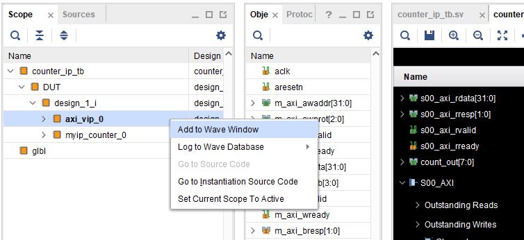
Add Desired Signals to Waveform
Once these signals are added to the waveform, zoom out of the waveform so you can see several clock cycles on the screen.
On the waveform, if you hover over the
M_AXIit will tell you what master axi it is referring to (this will be important once you create more advanced DUTs). TheM_AXIin this case is referring to theaxi_vip. This means that in the testbench whenever you use the master agent to perform write or a read it will show up here in the waveform.For this simple counter DUT, the first command we had the
axi_vipperform was to enable the counter. You can see in the that theaxi_vipinitiated a write to the address of44A0_0000and the data it sent was a 1, as shown in the figure below outlined in red.
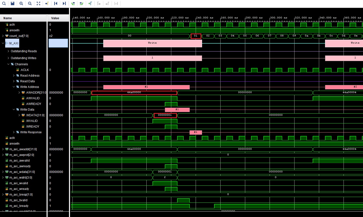
Simple Counter Waveform of Enable
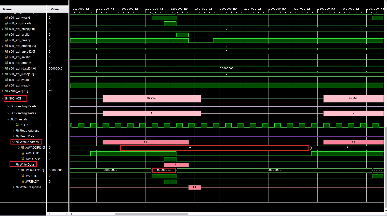
From there, you can scroll down on the waveform to see the
S_00signals. These are the signals for the slave simple counter. It shows that in the slave, the write address is 0 and the data is 1, which is completed at about 220ns. This is what we expect because that is what we need to do to start this simple counter IP. If you return to the previous image you can see that the counter began counting at about 240ns. You can continue to read the waveforms in this manner.
Note
Ensure you are running the simulation long enough to see all actions performed in the testbench by using the TCL command run -all!
Simple Counter Waveform of Enable pt.2